Summarize 400G and 100G Single Lambda Transceiver Interfaces
In this blog, we summarized the most common interfaces for 400G multimode and singlemode transceivers as well as the corresponding 100G transceivers. Please note that DAC/AOC cables or coherent transceivers are not coverd in this article.
Form-factors for 400G transceivers
QSFP-DD and OSFP are the 2 common form factors for 400G. For the transceiver interfaces in this post, both form-factors are performing equally well.
The main features and Benefits of QSFP-DD Form Factor
The QSFP-DD has an advantage in that is more widely adopted and offers simpler backward compatibility.
The main features and Benefits of QSFP-DD Form Factor
The OSFP has an advantage in a clearer way to 800G and superior thermal performance.
The common part for 400G QSFP-DD and OSFP transceivers is that the electrical interface to the host is operated at 8x50G PAM4. (Note: OSFP MSA Specification)
Multimode (MM) 400G transceivers and interfaces
The most interesting 400G multimode interfaces are the SR8 (IEEE802.3cm) and SR4.2 interfaces.
400G Multimode transceivers overview
| Optical Modulation | PMD Type | Reach | Fiber Type | Optical Connector | No.of Fibers | No. of Wavelengths |
| 8x50G PAM4 | 400G SR8 | 100m | MMF | MPO-16; 2 row MPO-12 | 16 | 1x 850nm |
| 8x50G PAM4 | 400G SR4.2 | 100m | MMF | MPO-12 | 8 | 2 (850nm/910nm) |
SR8:
“SR” refers to 100m reach using multi-mode fiber, and “8” implies there are 8 optical channels on 8 separate fibers. A total of 16 fibers (8 Tx and 8 Rx) are needed as each optical channel operates at 50G PAM4. The SR8 module uses either an MPO-16 connector or a 2 row MPO-12 connector to connect to 8 fiber pairs. The most common implementations use 2 row MPO-12.

SR4.2:
“SR” refers to 100m reach using multi-mode fiber, and “4” implies there are 4 optical channels on 4 separate fibers and “2” implies that each channel uses 2 wavelengths. A total of 8 fibers are needed as each optical channel operates at 2x50G PAM4. The wavelengths are bi-directional and multiplexed. The SR4.2 module uses an MPO-12 connector and the big driver for SR4.2 is that it enables the continued use of existing installed cables.

SR4.2 in an MPO-12 connector. Each fiber carries 2x50G bidirectional PAM4 signals. SR4.2 also supports MDC and SN connector interfaces and please check the QSFP-DD MSA for more information.
Singlemode (SM) 400G transceivers and interfaces
There are many more singlemode 400G interfaces and they can be divided in two groups. One group that operates optical 8x50G PAM4 channels, the other group operates optical 4x100G PAM4 channels.
8x50G PAM4 SMF 400G transceivers VS 4x100G PAM4 SMF 400G transceivers

Towards the host, both approaches use 8x50G PAM4 electrical lanes as defined in the form-factor. Both approaches also use DSPs as CDRs (analogue CDRs are not established) or as combined Gearbox & CDR. The difference is signaling rate on the line side and the number of used lasers.
Summary table for 400G Singlemode transceiver interfaces:
| Optical Modulation | PMD Type | Reach | Fiber Type | Optical Connector | No.of Fibers | No. of Wavelengths |
| 8x50G PAM4 | 400G 2FR4 | 2km | SMF | 2x CS connector | 4 | 4 CWDM4 |
| 8x50G PAM4 | 400G FR8 | 2km | SMF | LC Duplex | 2 | 8 LANWDM |
| 8x50G PAM4 | 400G LR8 | 10km | SMF | LC Duplex | 2 | 8 LANWDM |
| 4x100G PAM4 | 400G DR4 | 500m | PSM/SMF | MPO-12,4xSN,4xMDC | 8 | 1x 1310nm |
| 4x100G PAM4 | 400G 4xFR1 | 2km | PSM/SMF | MPO-12,4xSN,4xMDC | 8 | 1x 1310nm |
| 4x100G PAM4 | 400G 4xLR1 | 10km | PSM/SMF | MPO-12,4xSN,4xMDC | 8 | 1x 1310nm |
| 4x100G PAM4 | 400G FR4 | 2km | SMF | LC Duplex | 2 | 4 CWDM4 |
| 4x100G PAM4 | 400G LR4 | 10km | SMF | LC Duplex | 2 | 4 CWDM4 |
Singlemode transceivers using 8x 50G PAM4
Three common interfaces exist: FR8, LR8 and 2x FR4. FR8 and LR8 were the first 400G singlemode interfaces becoming available. The “8” indicates the use of 8 wavelengths with each one operating at 50G PAM4. “FR” indicates 2km and “LR” indicates 10km. The 8 wavelengths are multiplexed into one fiber and the FR8 and LR8 transceivers use duplex LC interfaces.
The 2x FR4 transceiver also uses 8 lasers but is divided into 2 groups with four wavelengths (following the 200G FR4 standard). These 2 groups are multiplexed each into a fiber and the transceiver offers a 2x200G interface on 2 CS connectors.
There is however a tradeoff when using eight laser (8x50G) solutions. On the one hand they offer improved link budgets in some scenarios, but on the flip side the total laser cost is higher per module (8 instead of 4). The optical packaging is more complex which results in a lower yield and higher production cost. By contrast, 4x100G modules have lower power consumption and simpler thermal handling with the net effect that there is now a shift towards the adoption of 4x100G solutions.
Singlemode transceivers using 4x100G PAM4
4x100G transceivers are the current market focus and the common part is that the line side uses 4 lanes with 100G PAM4. Here we can group the transceivers into “Multi Fiber” and “Two fiber” types. The key element in these transceivers is the DSP with its gearbox function. Four common interfaces exist: DR4, 4xDR1, 4xFR1, 4xLR1, FR4 and LR4
In a DR4 transceivers the DSP converts the 8x50G PAM4 electrical host signals into 4x 100G electrical lanes towards the optical engine. At the same time the DSP acts as a CDR. In a DR4 the optical engine (EML lasers or Silicon Photonics SIP based) generates and terminates the optical lanes. Each lane operates at 1310nm and requires one fiber, thus the transceiver interface needs to have 8 fibers.

DR4, 4xDR1, 4xFR1, 4xLR1: Break-out function/application
Multifiber transceivers can either be operated as a 400G interface using 4+4 fibers in parallel to transmit 400G, or as a 4x100G interface acting as four independent 100G interfaces, with each interface using 1 pair of fibers. This function is often referred to as “Break-out Support”.
There is no official difference in interface nomination, but sometime the DR4 is also referred as 4xDR1 to clarify the support of break-out functions.
· DR4 (4xDR1) targets 500m transmission
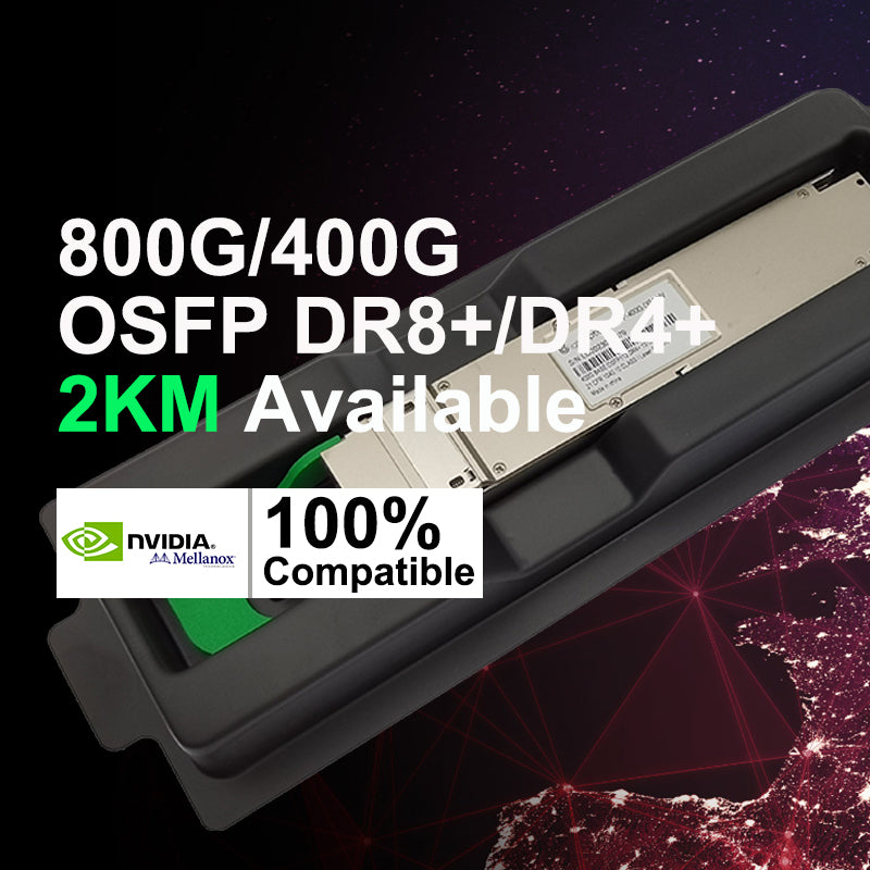
· 4xFR1 targets 2km transmission (this interface is also call eDR4, XDR4, DR4+)
· 4xLR1 targets 10km transmission.

FR4 and LR4
The basic function of the DSP is the same in FR4 and LR4 transceivers as in the DR4, but now 4 wavelengths (CWDM4 grid) are being used instead of 4x 1310nm signals and a multiplexer is added to combine these CWDM signals together. By this, the number of required fibers is reduced to 2 (TX + RX). The transceivers have duplex LC interfaces.

The FR4 standard is set, but for LR4 two different routes exist and we most likely will end up with two versions, one with for 6km (IEEE) and one for 10km (100G lambda MSA).
The lower cost and power consumption of these 4x100G interfaces make them the likely choice for the near future.
MPO, MDC or SN interfaces
There are three common optical connector interface types: MPO-12, MDC, SN. All three are part of the QSFP-DD and OSFP MSAs.
The SN and MDC connectors are relatively new, but they have a potential for wide adoption.
The MPO-12 offers the possibility to reuse cabling from PSM4 installations. The SN and MDC connectors offer advantages in individual 100G cabling challenges.

Form-factors for 100G Single Lambda
QSFP28 and SFP-DD are the interesting form factors for 100G single lambda transceivers. QSFP28 is the first mover due to its wide adoption and installed base. SFP-DD offers a smaller next generation interface and is also suitable for low cost AOCs and DACs.
The electrical interface from a QSFP28 transceiver to the host is 4x25G NRZ, but the interface of the SFP-DD to the host is 2x50G PAM4.
QSFP28 vs SFP-DD

Multimode 100G Single Lambda
On the multimode transceivers there are SR2 and SR1.2 interfaces. These follow the same architecture as the SR8 and SR4.2, with only a quarter of the connections being used. The biggest difference is now the function of the DSP. In a QSFP28 the DSP converts 2x50G PAM4 lanes coming from the optical domain into 4x25G towards the electrical host interface. When doing this the KP4 FEC on the optical side also needs to be terminated or generated.
In the SFP-DD the DSP only needs to act as a dual lane CDR without interfering with the KP4 FEC.
As connector interfaces the MPO, SN or MDC offer suitable approaches. For SFP-DD transceivers the SN and MDC offer slight advantages.
Singlemode 100G Single Lambda
For singlemode applications the line side now acts as a 100G PAM4 single lambda interface able to interoperate with a breakout of the 4x100G QSFP-DD interface. Also, here there are 2 key differences between QSFP28 and SFP-DD. In the QSFP28, the optical 100G lambda is terminated and converted into an electrical 4x25G NRZ interface. The DSP needs to terminate/generate the KP4 on the optical side. In the next step the DSP needs to act as 1:4 gearbox generating a 4x25G NRZ interface. On the electrical host side, the DSP needs an option to enable or disable the KR4 FEC for legacy 100G ports.
In the SFP-DD case the DSP just acts as 1:2 gearbox, but the KP4 FEC is not generated or terminated. This is done in the host equipment.
Today, 100G single lambda transceivers are available in three flavors: DR1 (up to 500m), FR1 (up to 2km) and LR1 (up to 10km).
Summary table for 100G single lambda transceiver interfaces:
| PMD Type | Fiber Type | Reach | Color | Optical Connector | Wavelength | Optical Modulation |
| DR1 | SMF | 500m | Yellow | LC | 1310nm | 100G PAM4 |
| FR1 | SMF | 2km | Green | LC | 1310nm | 100G PAM4 |
| LR1 | SMF | 10km | Blue | LC | 1310nm | 100G PAM4 |
Latch colors
Most vendors have decided to follow the latch colors from the OSFP MSA. The latch colors are defined by medium and distance and not by the optical interface.
| Type | Reach | Color |
| DAC | Black | |
| AOC | Grey | |
| MMF 400G transceiver | Beige | |
| SMF 400G transceiver | 500m | Yellow |
| SMF 400G transceiver | 2km | Green |
| SMF 400G transceiver | 10km | Blue |
| SMF 400G transceiver | 40km | Red |
| SMF 400G transceiver | 80km | White |
Summary
Soon we most likely will see which types become the preferred customer choice. I will not be surprised if at the end the SR8, DR4 (500m and 2km), FR4 and LR4 are the dominant versions complemented by coherent ZR.


