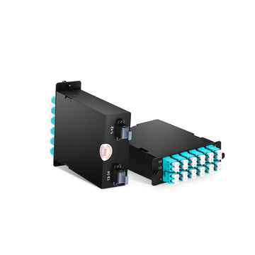
Fiber Optic Splitter

Fiber optic splitter is an optical passive device used to realize the splitting and combining of optical signals. Fiber Splitter distributes the light energy which transmitted in one fiber to two or more fibers in a set ratio, or combines the light energy which transmitted in multiple fibers into a single fiber.

LightOptics®

PLC splitter

PLC splitters are used to evenly divide one or two optical signals into multiple optical signals.

LightOptics®

Hybrid FBT+PLC splitter

Choose from various options by customized splitting ratio FBT splitter and PLC splitter.

LightOptics®

200°C high temp splitter

with Polyimide (PI) Coated Fibers which is for use in a temperature range of −190 °C to +385 °C

PLC Working Principle

When a single mode fiber conducts an optical signal, the light energy is not concentrated in the core, there are a little of light will transit through the cladding layer. When the cores of two fibers are close enough, the mode field of the light transmitted in one fiber can enter the other fiber, and the optical signal is redistributed in both fibers.

Optical fiber splitter light transmission is bi-directional, also the loss value is inidependent of the transmission direction. Whether the optical signal is transmitted from the input of the optical splitter downstream to the output or from the output upstream to the input, the loss value is the same in both transmission directions. Therefore, we only need to measure the loss value in one direction of the optical splitter.
PLC chip is the key component of a fiber PLC splitter. It consists of three layers: a substrate, a waveguide and a cover. The waveguide plays a key role in the splitting process that allows a specific percentage of light to pass through. So the signal can be divided equally. It is available in 1xN (N=2, 4, 8, 16, 32, 64) and 2xN (N=2, 4, 8, 16, 32, 64) splitting ratios. The figure below shows the typical design of a 1×8 PLC splitter chip.
LightOptics®
LightOptics®

What Is The Difference of FBT vs PLC Splitter

FBT vs. PLC Fiber Optic Splitters – What’s The Difference?

FBT vs. PLC Fiber Optic Splitters – What’s The Difference?

FBT vs. PLC Fiber Optic Splitters – What’s The Difference? The past few years have seen huge leaps in fiber-optic communications technology advancements that cater to the ever-accelerating demand for better and more...
What Is PLC fiber optic splitter?

What Is PLC fiber optic splitter?

Optical fiber splitter is an optical passive device that splits an optical fiber signal into multiple optical signal outputs. It can split an incident beam into two or more beams, including multiple inputs...

How To Use PLC Splitter In PON Network

Optical splitter is the core optical device in passive optical network (PON) system, widely used in fiber-to-the-home (FTTH), which has two different distribution methods in FTTH network: centralized distribution and cascaded distribution.

Centralized distribution

Centralized distribution has the advantages of high flexibility, low cost and easy maintenance, and is generally suitable for use in the city center or town with a high concentration of users.

Cascaded distribution

Cascade distribution has the advantages of low user access cost and flexible adjustment of splitting ratio, generally suitable for use in villages with more dispersed users.

Optical fiber splitter can be placed at different locations in a PON based FTTH network, which involves using either a centralized (single-stage) or cascaded (multi-stage) tap configuration in the distribution portion of the FTTH network. In fact, both approaches have their own advantages and disadvantages. So which one should you deploy? Below are comparison
Centralized distribution typically uses a combined split ratio of 1:64, 1:2 splitters at the local end, and 1:32 in the cabinet. these single-stage fiber splitter can be placed in multiple locations in the network or installed in a central location. In most cases, however, centralized plc splitter are placed in the external plant (OSP) to reduce the total amount of fiber required. The active port of the OLT (optical line terminal) in the central office (CO) will connect/splice to the fiber leaving the CO. The fiber passes through a different enclosure to the input port of a fiber optic splitter that is normally placed in the cabinet. The output port of this fiber splitter enters the FTTH distribution network and reaches the potential customer’s home through different enclosures and indoor/outdoor terminal boxes called ONTs (Optical Network Terminals). Thus, in this centralized split topology, the PON connects one OLT port to 32 ONTs.
LightOptics®
LightOptics®
The cookie settings on this website are set to 'allow all cookies' to give you the very best experience. Please click Accept Cookies to continue to use the site.
You have successfully subscribed!
This email has been registered